
- By Admin
- admin
-
 Construct Ion
-
 0 Comments
- Industry News
- 5137
Shell-and-Tube Heat Exchanger: Structure, Working Principle, Operation, and Maintenance Guide
1. Shell-and-Tube Heat Exchanger Structure and Working Principle:
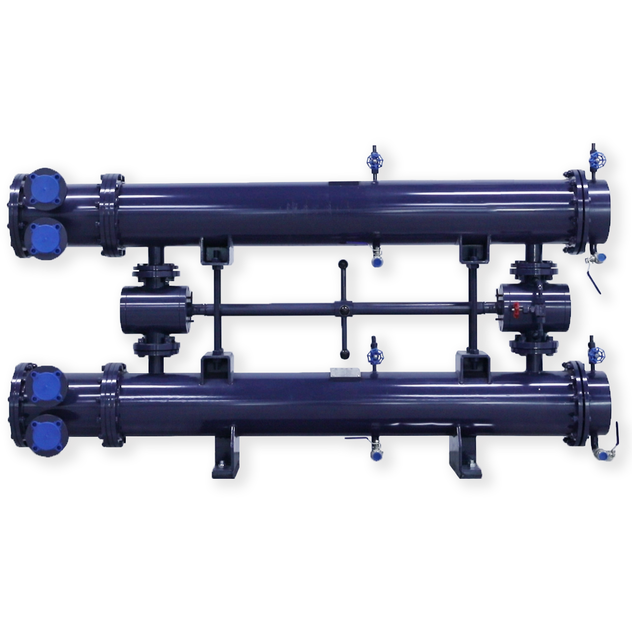
The shell-and-tube heat exchanger consists of two main parts: the external shell and the internal heat exchanger body. Due to differences in specific structural design, it is classified by external connection type into threaded and flanged types; by installation type into horizontal and vertical types; and by heat exchanger tube structure into bare tube and finned tube types, among others, all selected according to specific conditions.
The external shell includes: the shell body, the front water distribution cover, and the rear return water cover. It is equipped with inlet and outlet oil pipes and inlet and outlet water pipes, and also includes drain plugs for oil, water, and air, zinc rod mounting holes, and thermometer interfaces.
The heat exchanger body consists of heat exchanger tubes, a fixed tube sheet, a floating tube sheet, and baffles. The heat exchanger tubes are connected to the fixed and floating tube sheets at both ends; the fixed tube sheet is connected to the outer body flange, while the floating tube sheet can freely expand and contract within the shell to eliminate the effects of thermal expansion and contraction on the heat exchanger tubes due to temperature changes. The baffles serve to enhance heat transfer and support the heat exchanger tubes.
The hot medium of the shell-and-tube heat exchanger enters through the inlet pipe on the shell body, flows sequentially through the various baffle channels in a tortuous path to the outlet pipe. The cooling medium uses a double-pass flow, meaning the cooling medium enters through the inlet, passes through the water distribution cover into half of the heat exchanger tubes, then flows from the return water cover into the other half of the heat exchanger tubes, and then into the other side of the water distribution cover and the outlet pipe. During the double-pass flow process, the cooling medium absorbs the waste heat released by the hot medium and is discharged from the outlet, maintaining the working medium at the rated operating temperature.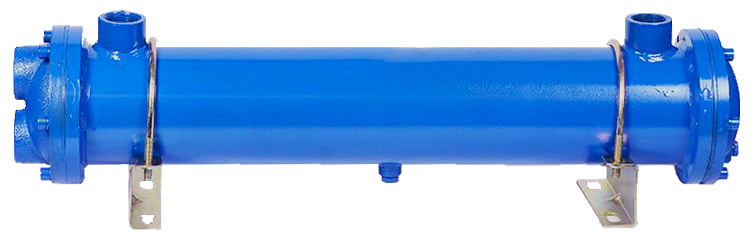
2. Usage and Operation
1. The heat exchanger's foundation must be strong enough to prevent settling. Sufficient space should be left at the fixed tube sheet end to allow for the removal of the tube bundle from the shell. The equipment should be installed according to lifting specifications. After leveling, tighten the anchor bolts and connect the inlet and outlet pipes for the hot and cold media.
2. Before starting the heat exchanger, air must be purged from the chambers to improve heat transfer efficiency. The steps are as follows:
(1) Loosen the vent plugs at the hot and cold media ends and close the media outlet valves;
(2) Slowly open the inlet valves for the hot and cold media until the media overflows from the vent holes, then tighten the vent plugs and close the inlet valves.
3. When the water temperature rises by 5-10℃, open the inlet valve for the cooling medium (Note: Avoid rapidly opening the water inlet valve, as a large flow of water through the heat exchanger will cause a poorly conductive "supercooled layer" to form on the heat exchanger surface). Then open the outlet valve for the hot medium to allow it to flow. Adjust the flow rate of the cooling medium to maintain the hot medium at the optimal operating temperature.
4. If electrochemical corrosion occurs on the cooling water side, a zinc rod can be installed at the designated location.
5. A filtration device should be installed before the heat exchanger if the medium is dirty.
6. The pressure of the medium being cooled should be greater than the pressure of the cooling medium.
3. Maintenance and Repair
1. After prolonged operation, scale will accumulate on the surface of the cooler tubes, increasing thermal resistance and flow resistance, leading to a gradual decrease in heat exchange performance and eventually failing to meet requirements. Clearly, the focus of maintenance should be on scale removal. Several cleaning methods are introduced here:
(1) Mechanical methods:
a. Using an electric tube cleaning tool. This involves an electric motor driving a flexible shaft in a rotating motion. A nylon brush or wire brush is attached to the end of the shaft for rotational scrubbing. Water is injected around the shaft through a watertight cover to promptly wash away loose scale.
b. Using a round pipe with a wire brush welded to one end, similar in diameter to the inner diameter of the tube. The brush is rotated and pushed through the tube. The scale accumulates in the inner cavity of the pipe, preventing the scale from becoming thicker and making further pushing more difficult. This method is commonly used, but it is labor-intensive.
(2) Using a high-pressure pump (pressure 10-20 MPa) to spray high-pressure water for flushing. This method is quite effective and is mainly used for cleaning between tubes.
(3) Using sponge balls for automatic cleaning of the heat exchange tubes. Sponge balls of different hardness are used depending on the type of scale. For particularly hard scale, a sponge ball with a "belt" of abrasive material can be used. The principle is that the relatively soft and elastic sponge ball enters the heat exchange tube, and the compressed ball contacts the inner wall of the tube. The relative motion between the ball and the tube wall continuously rubs the tube wall, removing the deposits.
(4) Chemical cleaning methods:
a. For oil-side cleaning, trichloroethylene solution can be used for reverse circulation cleaning. The solution pressure should not exceed the rated working pressure. The cleaning time depends on the amount of scale. Then, clean water is introduced into the cooler until the outflowing water is clean.
b. Using carbon tetrachloride immersion. The solution is poured into the cooler, and after 15-20 minutes, the color of the solution is observed. If it is heavily contaminated, the solution is replaced with fresh solution and the immersion is repeated until the outflowing solution is similar in color to clean solution. Then, rinse repeatedly with clean water. This cleaning should be performed in a well-ventilated environment to avoid poisoning.
2. Most cooler malfunctions are caused by problems with the cooling tubes. Due to corrosion, cavitation, and wear, the pipe walls can become thinner and perforated, and connections and other mechanical parts can be damaged due to thermal expansion and contraction, and vibrations caused by fluid movement. When a cooler tube breaks, the two media will mix, and repairs should be carried out promptly. The repair methods include:
(1) Locate the damaged cooler tube and plug both ends with tube plugs. The taper of the tube plug should be between 3 and 5 degrees, and the hardness of the tube plug material should be less than or equal to the hardness of the tube. The total number of plugged tubes should not exceed 10% of the total number.
(2) Remove the damaged tube and replace it with a new one, then re-expand the connection.
(3) If there is leakage at the connection between the tube end and the tube sheet, the connection should be re-expanded. If the corrosion is severe, the tube bundle should be replaced.
3. Coolers that are shut down for the winter should have all the media drained from the cavity to prevent freezing and cracking.
4. Disassembly and reassembly of the cooler should be carried out according to the following steps:
(1) Close the inlet and outlet oil and water valves, drain the remaining media, and then remove the cooler from the system.
(2) Remove the return water cover and the water distribution cover, and check the sealing rings, cooler tube damage, and scaling. If only tube plugging or cooler tube replacement is required, this can be done immediately. If the cooler tube bundle needs to be removed, it must be moved out from the fixed tube sheet direction (for large coolers, the vertical position (with the fixed tube sheet facing downwards) can be used, and then the shell can be lifted using a crane to expose the tube bundle).
(3) Reassembly should be carried out in the reverse order of disassembly. The sealing rings should generally be replaced with new ones.
(4) After installation, airtightness tests should be performed separately on the oil side first and then the water side. The test pressure should be 1.2 times greater than the actual working pressure.
Troubleshooting
Decreased Heat Exchange Performance
1. Faults and Causes
(1) Insufficient water flow in the cooler;
(2) Air accumulation in the chamber;
(3) Increased scaling on the heat exchange tube walls, increasing flow resistance and thermal resistance;
(4) Oil emulsification or oil-water mixture in the cooler water;
(5) Leakage at the flange connection between the return water cover and the water distribution cover;
(6) Corrosion at the connection between the moving and fixed tube sheets and the heat exchange tubes, resulting in loss of sealing.
2. Troubleshooting Methods
(1) Faults and Causes
① Open the water inlet valve wider;
② Clean the blocked pipelines, valves, filters, or heat exchange tubes;
(2) Unscrew the plug to release air;
(3) Use appropriate methods to clean the scale on the inner and outer surfaces of the heat exchange tubes;
(4) ① Replace the heat exchange tubes;
② Plug the damaged tubes with tube plugs (number not exceeding 10);
(5) ① Tighten the screws on both end covers;
② Replace the sealing gasket;
(6) Replace the tube bundle.